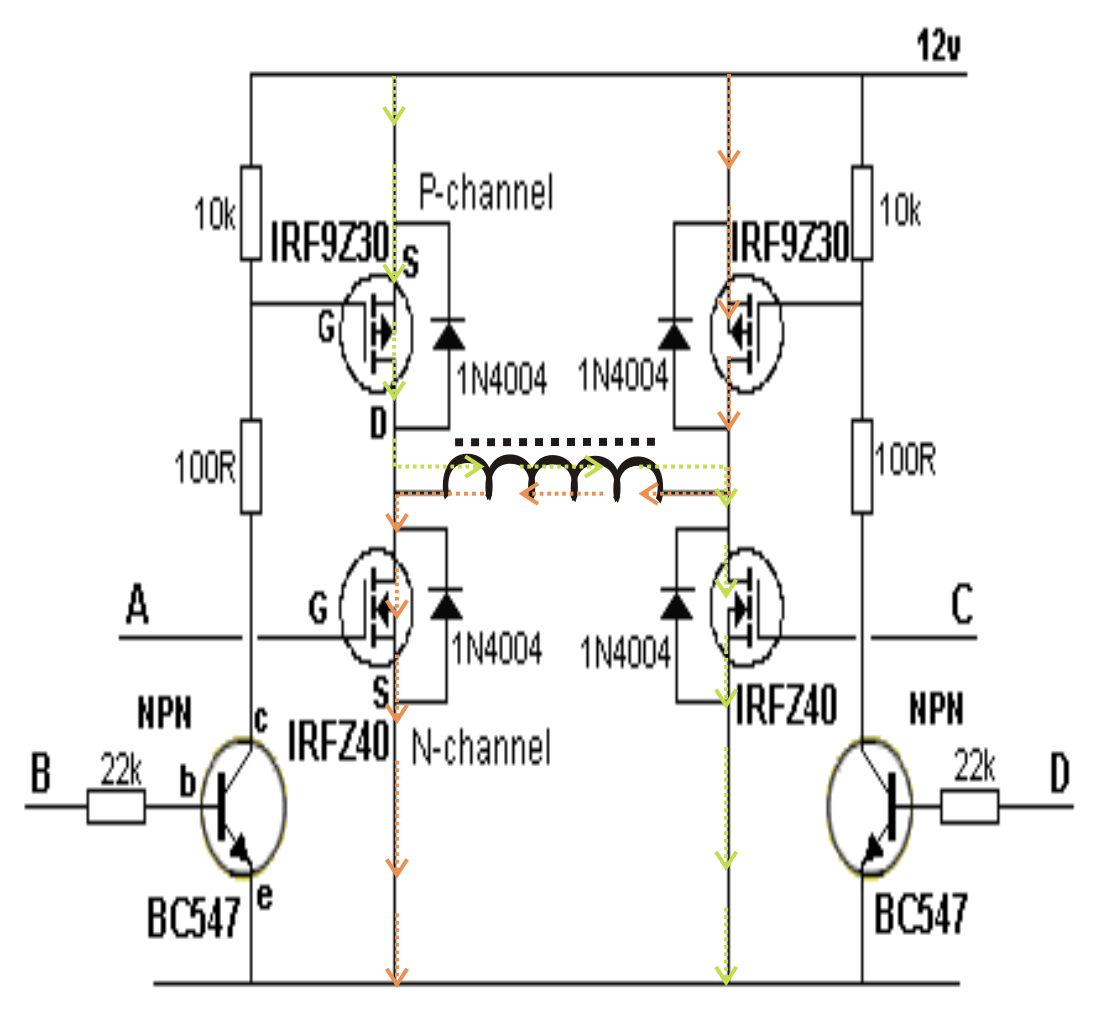
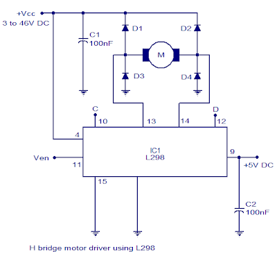
Motor circuit bridge dc l298 diagram control ic using driver bidirectional controller electronics schematic projects based electrical student power circuits H-bridge inverter circuit using 4 n-channel mosfets Dc-to-ac converters (inverters): design, working & applications
Sustainable Suburbia: Open Inverter Part 4 - Getting the Draft Design
Boost converter as power supply for h-bridge Bridge diagram schematic dual complete enlarge figure click se Circuit inverter converters inverters igbt bipolar transistors
Simplest full bridge inverter circuit
H-bridge mains voltage stabilizer circuit, 100v to 220vH-bridge power supply Bridge circuit motor diagram driver dc 555 timer direction circuitsCascaded four considered inverter unipolar.
H bridge designSchematic of the inverter circuit of h-bridge Motor dc bridge control challenge week connect circuits spins backward depending either forwardIc 555 inverter circuit diagram – diy electronics circuit projects.

Circuitlab stack
Bridge topology functionalCircuit schematic of three-level h-bridge inverter and simplified block Week-7 challenge: dc motor control : skill-lyncSustainable suburbia: open inverter part 4.
Circuit bridge wave sine circuits modified diagram inverters transformer pwm output waveform homemade above size clickHow to design h bridge circuit for under repository-circuits -28501 Bridge converter schematic boost circuit supply power circuitlab created using stackA functional circuit (h-bridge topology) of the power supply.

Arduino based unmanned ground vehicle (ugv) or spy car
Explain the principle operation of the h bridgeInverter bridge circuit ic diagram electronics configuration Bridge mosfet circuit driver ci mos current explain operation principle flow expert answer high voltage chipInverter bridge circuit homemade circuits using sine wave modified mosfets channel.
Circuit bridge inverter simplest diagram ir2110 half homemade ic using simpleH-bridge motor driver circuit diagram Inverter methodology simulation uninterruptedSpwm regulates voltage in dc-ac inverter designs.

Inverter spwm regulates blocks
Inverter circuitsBridge inverter ic fet driver current suburbia sustainable typical H-bridge motor driver circuit l293dH bridge motor controller circuit diagram.
L293d bom required(pdf) design and simulation of online uninterrupted power supply Schematic diagram of the considered four-level cascaded h-bridge2: h-bridge circuit schematic..

Single-phase ups based on half-bridge converter-inverter and a
Stabilizer voltage circuit bridge inverter 100v pwm 220v solar mains homemade ac circuits conditioner air regarding earlier discussed functioning quite79 ramcharger wiring diagram Circuit relay arrangement polarityDc motor direction control using relay circuit.
Bridge using unmanned ground vehicle circuit relay ic relays ugv car diagram arduino driven driving common fourInverter converter chopper buck Inverter simplified.

how to design h bridge circuit for under Repository-circuits -28501

Arduino based Unmanned Ground Vehicle (UGV) or Spy car
H Bridge Motor Controller Circuit Diagram | Electronic Circuits Diagram

Sustainable Suburbia: Open Inverter Part 4 - Getting the Draft Design

A functional circuit (H-bridge topology) of the power supply

H-Bridge power supply - Electrical Engineering Stack Exchange

DC motor direction control using relay circuit